9.1.5 Seal Washout – beginner guide¶
In one sentence
Connect and disconnect the coupling 20 times in each flow direction while hot water is pushed through it at twice the rated flow and 6.9 bar(g), and check that no seal is pushed out of its groove and nothing leaks.
See it move
The interactive page shows this rig with every value and length for your size, and animates the set-up and the test.
Running the test?
Use the interactive Test logger. It shows the values for your size, keeps the tick-boxes, checks the 30 psi spike limit on every cycle, decides pass/fail and exports the protocol.
Source: OCP UQD Specification v2.0.0 §9.1.5 (Figure 14). Full engineering instruction: 06 Seal Washout.
1. At a glance¶
-
Cycles
20 + 20 20 in each flow direction, same pair
-
Pressure
6.9 bar(g) 100 psi(g) operating pressure
-
Flow
2 × rated see the table for your size
-
Temperature
60 °C water or PG25
-
Speed
40 ± 10 mm/s connect and disconnect
-
Samples
5 pairs 3 pairs for cross-verification
2. What does the test prove?¶
Inside each half of the coupling there is a valve with a rubber seal (O-ring) sitting in a groove. When you disconnect under flow, water rushes past the seal for a fraction of a second. If the groove is badly designed, the rushing water can pull the seal out of its groove – that is a seal washout. The coupling will then leak.
In a data centre this happens when a technician pulls a running server out of a live cooling loop. This test recreates that situation in the lab, with some margin: double the normal flow and hot fluid.
Why 60 °C and 2 × flow?
Hot rubber is softer and fast water pulls harder. Testing above normal conditions shows that the design has margin, not just that it survives a good day.
3. The test rig¶
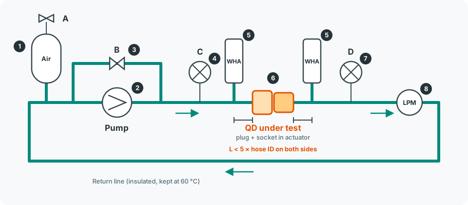
Tap the picture to open it full size.
Not sure what a symbol means? See the Symbols page.
| No. | Part | What it does | Beginner check |
|---|---|---|---|
| 1 | Accumulator + valve A | A tank with an air cushion. Valve A is used to pump up the loop pressure. The air cushion keeps the pressure steady when the coupling opens and closes. | Pre-charge about 4–5 bar (internal proposal) |
| 2 | Pump | Pushes the fluid round the loop. Speed-controlled. | Can reach 2 × rated flow at 6.9 bar(g) |
| 3 | Bypass valve B | Lets the pump keep running when the coupling is disconnected, and is used to trim the flow. | Never fully closed while the QD is disconnected |
| 4 | Pressure gauge C | Measures pressure before the coupling. This is the one you watch for 6.9 bar(g) and for the pressure spike. | Logs at ≥ 1 kHz (internal proposal) |
| 5 | WHA × 2 | Water hammer arrestors. Small shock absorbers that soften the pressure spike when the valve slams shut. | Mounted as close to the QD as possible |
| 6 | QD under test | The plug and socket, held in a linear actuator that pushes them together and pulls them apart. | Coaxial, no side load |
| 7 | Pressure gauge D | Measures pressure after the coupling. | Logged together with C |
| 8 | Flow meter (LPM) | Shows the flow in litres per minute. | Range up to ≥ 40 L/min |
Stop – distance to the WHA
The pipe between each WHA and the coupling must be shorter than 5 × the hose inside diameter (L < 5 × ID). We use L = 30 mm on every size (BS-010). For size 02 the limit is only about 31.7 mm, so 30 mm works only if the measured hose ID is at least 6.0 mm. If L is too long, the spike will be too high and the test is not valid.
4. Values for your size¶
| What | Value |
|---|---|
| Rated flow | 2.27 L/min |
| Test flow (2 ×) | 4.54 L/min (1.20 GPM) |
| Allowed flow window | 4.54 – 4.77 L/min (+5 % / −0 %) (internal proposal) |
| Hose inside diameter | 6.35 mm (1/4") (internal proposal, MD-023) |
| Max length WHA ↔ QD | < 31.7 mm |
| Expected ΔP across QD | ≈ 1.1 bar (16 psi) |
| What | Value |
|---|---|
| Rated flow | 6.44 L/min |
| Test flow (2 ×) | 12.88 L/min (3.40 GPM) |
| Allowed flow window | 12.88 – 13.52 L/min (+5 % / −0 %) (internal proposal) |
| Hose inside diameter | 9.525 mm (3/8") (internal proposal, MD-023) |
| Max length WHA ↔ QD | < 47.6 mm |
| Expected ΔP across QD | ≈ 0.66 bar (9.6 psi) |
| What | Value |
|---|---|
| Rated flow | 11.36 L/min |
| Test flow (2 ×) | 22.72 L/min (6.00 GPM) |
| Allowed flow window | 22.72 – 23.86 L/min (+5 % / −0 %) (internal proposal) |
| Hose inside diameter | 12.70 mm (1/2") (internal proposal, MD-023) |
| Max length WHA ↔ QD | < 63.5 mm |
| Expected ΔP across QD | ≈ 0.51 bar (7.4 psi) |
| What | Value |
|---|---|
| Rated flow | 17.79 L/min |
| Test flow (2 ×) | 35.58 L/min (9.40 GPM) |
| Allowed flow window | 35.58 – 37.36 L/min (+5 % / −0 %) (internal proposal) |
| Hose inside diameter | 15.875 mm (5/8") (internal proposal, MD-023) |
| Max length WHA ↔ QD | < 79.3 mm |
| Expected ΔP across QD | ≈ 0.47 bar (6.8 psi) |
Same for all sizes: 6.9 bar(g) at C, max spike +30 psi (≤ 130 psi(g) / 8.96 bar(g) at C), 60 °C, 40 ± 10 mm/s.
5. The whole test as a flow chart¶
flowchart TD
    P[Prepare the rig<br/>F1–F8] --> S1[S1 Mated: start pump,<br/>set 2 × rated flow]
    S1 --> S2[S2 Stop pump,<br/>disconnect QD]
    S2 --> S3[S3–S4 Start pump,<br/>pressurise to 6.9 bar at C]
    S3 --> S5[S5–S6 Stop pump,<br/>connect QD]
    S5 --> T1{T1 Pump on:<br/>flow still 2 × rated?}
    T1 -- No --> S2
    T1 -- Yes --> T2[T2 Run 20 cycles<br/>connect + disconnect]
    T2 --> T4{Leak or<br/>washout?}
    T4 -- Yes --> F([FAIL – stop this pair])
    T4 -- No --> D{Both directions<br/>done?}
    D -- "No: only P→S done" --> R[Turn the pair round:<br/>flow S→P]
    R --> S1
    D -- Yes --> E[Inspect seals<br/>E1–E2]
    E --> OK([PASS for this pair])
    classDef fail fill:#ffcdd2,stroke:#c62828,stroke-width:2px;
    classDef pass fill:#c8e6c9,stroke:#2e7d32,stroke-width:2px;
    class F fail;
    class OK pass;
One cycle, close up¶
flowchart LR
    A["① Mated<br/>flow stable<br/>≥ 5 s"] --> B["② Pull apart<br/>40 mm/s<br/>log spike at C"]
    B --> C["③ Apart<br/>pressure stable<br/>≥ 5 s, look for drips"]
    C --> D["④ Push together<br/>40 mm/s"]
    D --> E["⑤ Flow back to<br/>2 × rated?<br/>check joint"]
    E --> A
The dwell times of ≥ 5 s are an internal proposal (MD-022); the specification does not give them.
6. Step by step¶
Phase 1 – Prepare (before the pump is started)¶
- F1 Check sample ID and marking. Photograph both valve seals (plug and socket).
- F2 UQD only: remove or bypass the latch so the actuator can pull the halves apart. Write down how.
- F3 Mount the pair so the flow goes plug → socket (P→S): fluid enters through the plug. Tighten terminations to the torque in Table 5.
- F4 Set the distance WHA ↔ QD to 30 mm on both sides and measure it. Must be < 5 × ID (see your size tab). Size 02: hose ID must be ≥ 6.0 mm.
- F5 Fill the loop and bleed out all air.
- F6 Heat to 60 °C and wait until the temperature is stable.
- F7 Set the actuator to 40 mm/s and check it with the position sensor (30–50 mm/s is OK).
- F8 Set the dwell times: ≥ 5 s mated, ≥ 5 s unmated (internal proposal).
Bleed while hot
Air comes out of the water when it is heated. Bleed again after F6, otherwise the pressure reading will bounce and the spike will look smaller than it really is.
Phase 2 – Set the operating point¶
- S1 With the QD mated: start the pump. Adjust pump speed and/or valve B until the flow meter shows the test flow for your size.
- S2 Stop the pump. Disconnect the QD.
- S3 Start the pump again (fluid now goes through bypass B).
- S4 Pump up the loop through valve A until gauge C shows 6.9 bar(g).
- S5 Stop the pump.
- S6 Connect the QD.
Why this order?
S1 sets the flow, S4 sets the pressure. Because changing one affects the other, you set them in separate steps and then check both again in T1.
Phase 3 – Run the test (direction P→S)¶
- T1 Start the pump. Check that the flow is still the test flow. If you had to adjust, go back to S2.
- T2 Run 20 cycles at 40 mm/s (see One cycle, close up).
- T3 Every disconnect: the spike at C must be no more than 30 psi above the pressure just before.
- T4 Watch for leaks and for a seal sticking out of a valve during all 20 cycles.
Stop – spike above 30 psi
The cycle is invalid, not failed (internal proposal, MD-024). Stop, adjust the WHAs, the accumulator pre-charge or the flow, and run that cycle again. Write it in the log.
Phase 4 – Reverse and repeat (direction S→P)¶
- T5 Only if there was no failure in P→S: turn the pair round so the fluid enters through the socket, then repeat S1 → T4.
Phase 5 – After the test¶
- E1 Photograph both valve seals again and compare with the photos from F1.
- E2 Optional: hold each half at 6.9 bar(g) for 3 min, unmated, and look for leaks (as 9.2.4).
- Fill in the protocol: 06 Seal Washout §9.
7. Pass or fail?¶
PASS
No leak and no seal washout in any of the 20 + 20 cycles. The product passes when all 5 pairs pass in both directions.
FAIL
- Leak: fluid drips or seeps from a closed valve (apart) or from the joint (together), more than the normal small drop at disconnect.
- Seal washout: a seal is fully or partly out of its groove, visible outside the groove, found in the loop, or the valve no longer seals.
A pair that fails in P→S is not run in S→P. It counts as failed.
The exact definitions of leak and washout are an internal proposal (MD-025).
8. Common mistakes¶
| Mistake | What happens | How to avoid it |
|---|---|---|
| Air left in the loop | Pressure and flow jump about; the spike is damped and looks too good | Bleed after heating, again after the first cycles |
| Pipe to WHA too long | Spike above 30 psi, cycle invalid | Mount the WHA directly on the adapter |
| Halves not lined up | Side load damages the seal; looks like washout but is a rig fault | Coaxial fixture, check before F5 |
| Flow drifts down | Test runs below 2 × rated, result not valid | Log the flow every cycle |
| Wet joint mistaken for a leak | False fail | Wipe the faces after each disconnect, then look |
| Medium not recorded | Report cannot be compared | Always write water or PG25 in the protocol |
Safety
The fluid is 60 °C at 6.9 bar. A failed seal gives a hot jet. Work behind a screen, wear eye protection and heat-resistant gloves, and release the pressure before you change samples. Keep hands away from the actuator; use the emergency stop.
9. Open points that affect this test¶
| ID | What is unclear | What we do for now |
|---|---|---|
| MD-009 | No tolerance on 60 °C | ± 3 °C |
| MD-022 | No dwell times per cycle | ≥ 5 s mated and unmated |
| MD-023 | Hose ID, UQDB alignment, which half moves | Hose ID as 9.1.4, coaxial at hard-stop, plug moves |
| MD-024 | Is the 30 psi limit a rig rule or a pass criterion? | Spike > 30 psi = invalid cycle |
| MD-025 | No definition of leak / washout | Definitions in section 7 |
| MD-028 | Gauge D not used in the procedure | Log both C and D |
| ER-014 | Unclear when the pump is restarted between S5 and T1 | Start the pump in T1 |
| BS-002 | Test hybrid (UQD plug + UQDB socket)? | Decision pending |
| BS-004 | Water or PG25 | Decision pending |
All items: 04 Backlog.