The test circuits and drawings in the specification use their own picture symbols. This page shows each one,
how it looks and what it means, with the figure where you will meet it.
Where does this come from?
The meanings are taken from OCP UQD Specification v2.0.0 and listed in full in
07 Symbols, which also shows where each meaning comes from (specification,
standard drawing practice, or our reading of the drawing). The pictures here are our own redrawing, made
to look like the figures. Where the specification does not define a symbol, the card says so.
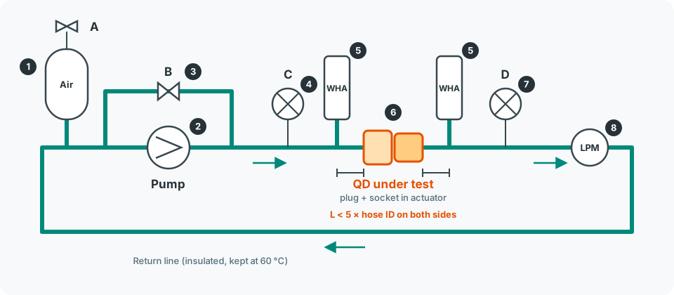
Used in the test circuits for 9.1.4 Pressure Drop (Figure 13) and 9.1.5 Seal Washout (Figure 14).
The teal line is the pipe or hose, the orange parts are the coupling that is being tested.
ValveTwo triangles tip to tip. Opens, closes or throttles the flow. A pressurises the loop through the accumulator. B is in the bypass and sets the flow.Figure 14 · 9.1.5Circulator pumpCircle with a triangle. The triangle points the way the fluid is pushed. Speed is adjusted to set the test flow.Figure 14 · 9.1.5Accumulator (air cushion)Upright capsule marked Air. Holds the loop pressure steady and takes up volume changes when the coupling connects and disconnects.Figure 14 · 9.1.5Pressure gauge (circle with cross)Pressure transducer in the loop, read in PSIG. C is before the coupling and is used to set 6.9 bar(g) and to read the disconnect spike. D is after it.Figure 14 · 9.1.5Pressure or temperature gauge (circle with pointer)Circle with a pointer. Same job as the cross version. Not named in the key of the figure.Figure 13 · 9.1.4WHA – water hammer arrestorUpright capsule marked WHA. A small shock absorber that softens the pressure spike when the valve slams shut. One on each side of the coupling, as close as possible (L < 5 × ID).Figure 14 · 9.1.5QD under test (dark bow-tie)Two filled triangles tip to tip: the coupling pair that is connected and disconnected by the actuator during the test.Figure 14 · 9.1.5Coupling under test (facing halves)Two valve halves facing each other. Item 1 in the key. The pressure drop is measured across it.Figure 13 · 9.1.4Flow meter (LPM)Circle marked LPM (litres per minute). Shows the test flow, for example 2 × rated flow.Figure 14 · 9.1.5Flow meter (circle with wave)Circle with a wavy line. Not named in the key of the figure.Figure 13 · 9.1.4Pressure tapSlanted arrow touching the pipe. Where the pressure is picked up. There are two, one on each side of the coupling (item 2).Figure 13 · 9.1.4Differential pressure deviceBox connected to both pressure taps. Measures the difference in pressure across the coupling (item 3).Figure 13 · 9.1.4Controlled fluid supplyBox with a pipe out. Gives a controlled flow of test fluid (item 4).Figure 13 · 9.1.4Drain / reservoirOpen-topped box at the end of the circuit where the fluid is collected.Figure 13 · 9.1.4Flow directionArrow on the pipe. In the 9.1.5 report P-S means plug to socket and S-P means socket to plug.Figures 13, 14Length LDimension arrow between two points. In the washout loop it is the pipe length from each WHA to the coupling: shorter than 5 × the inside diameter.Figure 13, 14
Putting it together: pressure-drop circuit (Figure 13)
Follow the fluid from left to right. The numbers match the cards above and the key in the specification.
Why the straight pipe lengths?
Turbulence from bends and fittings disturbs the pressure reading. L1 to L5 give the flow time to settle
before and after each pressure tap. The values are minimum lengths. See
05 Pressure Drop for how to build it.
Putting it together: seal washout loop (Figure 14)
Valves A and B, the accumulator, the pump, gauges C and D, two WHAs, the coupling under test and
the flow meter are the symbols from the cards above. The full step-by-step is in the
9.1.5 guide.
Used on the dimension drawings (Figures 4–10) and in Tables 1–4. The specification does not say which drawing
standard it follows (ASME Y14.5 or ISO GPS). We read them as ASME Y14.5 (backlog item MD-026).
Ø DiameterThe dimension is a diameter, not a length. ØB = the diameter called B.Figures 7–10, Tables 1–4± Bilateral toleranceAllowed deviation above and below the nominal value. Any value in the band is accepted.e.g. ±0.025+0.30 / −0.00 One-sided toleranceMay only deviate in one direction. SA (self-alignment) on the UQDB plug is allowed 0 to +0.30 mm.Table 4R RadiusRadius of a rounded corner or edge. R0.2-0.3 means any radius between 0.2 and 0.3 mm.Figure 8 Detail AnX Number of placesThe callout applies to n identical features. 2XØG = two features with diameter G.Figures 8, 10MIN / MAX Single limitOnly one side is limited. J MIN: this size or larger. R MAX: this size or smaller. The shaded side is accepted.Tables 1–4[MIN, MAX] IntervalThe value must lie anywhere inside the square brackets. Used for dimension C on sizes 06 and 08 instead of ±0.025.Tables 1, 3( ) or REF Reference dimensionDerived from other dimensions. Shown for information, not inspected and has no tolerance.e.g. (S), (T), (ØRR)Ⓔ Envelope requirementThe feature must fit inside a perfect cylinder of its maximum material size (dashed). Used on sealing surfaces such as ØH, ØL and 2XØG.Figures 8, 10TSC Theoretical sharp cornerMeasure to the point where the two surfaces would meet (dot), not to the real rounded or chamfered edge.NOTE 6 · AA, T, U.000 Zero datumThe origin for position dimensions: the plug tip or the socket face. P, N, Q, J, BB … are measured from this line.Figures 8, 9, 10HEX HexagonA hex nut or wrench flats, seen from the end. Size across the flats is given in Table 5.NOTE 332Ra MAX Surface roughnessCheck-mark on the surface. The surface must be at least this smooth. Unit is missing in the spec: 32 µin = 0.8 µm is assumed (MD-027).NOTE 2 · sealing surfacesCL Centreline (dash-dot line)Long line, short dash, long line. Marks the axis of a round part, the line it is turned around.Figures 5, 10X–X Section lineImagine the part cut along the dash-dot line. The arrows show the viewing direction; the cut is shown as SECTION X–X.Figures 7–10Hatching Section fillDiagonal lines show the surface where the part is cut open in a section view. Empty areas are air or fluid.All section viewsSEE DETAIL A Detail calloutA circle marks a small area that is shown enlarged in another view, DETAIL A, B or C.Figures 8, 9, 10Keep-in zoneA dashed outline the part must stay inside. Any shape is allowed within it. Used for the maximum outer size CC and length DD.NOTE 5 · CC, DDR0.3 MIN or equivalent chamferBreak a sharp edge with either a rounded corner of at least R0.3 mm, or a chamfer that removes at least as much material.Figures 8, 10 Detail B
Letters such as A, B, C, G, H, J, L, M, P, Q, R name a length, diameter, position or angle on the plug and
the socket. Their meaning, tolerance and the figure they belong to are listed in
07 Symbols, section 3, and the values per size are in
02 Parameters, section 5.